Circuit Constructions Aim: To investigate parallel circuits, voltage and current. Keywords: Parallel Circuit, Voltage, Current, Ammeter, Voltmeter This lesson we continued modelling series and parallel circuits off of the diagrams below. We also recorded the volts, amps and any brightness changes that occurred between different circuits. Here are the findings and comparisons between the circuits: Circuit 1 includes only one light bulb, connected to a switch and a transformer. Being the only electrical component in the circuit, the light bulb was able to use all 12 volts. This resulted in the light being so bright, that it turned white. However, as soon as we added a second light bulb, as seen in Circuit 2, each light was only able to use 6 volts, resulting in a much dimmer, yellow light.
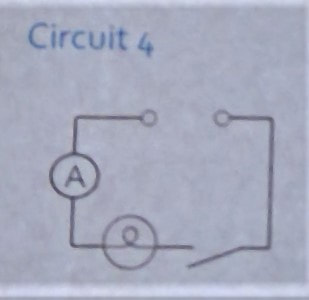
Circuit 3 is identical to Circuit 1, however it has an added ammeter. The ammeter is placed between the switch and transformer, and measures the amps or current that is flowing through the circuit. In this circuit, a total of 0.7 amps were recorded. Now in Circuit 4, we moved the ammeter to between the transformer and light bulb to record any changes. However, the current was still 0.7 amps and this is due to there being only one possible path in a series circuit. Circuit 5, as seen below, is the same as Circuit 4, with an added light bulb between the transformer and the switch. In Circuit 5, a total of 0.45 amps was recorded. This was less than Circuit 4 due to the added resistance of the first bulb.
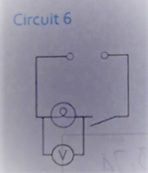
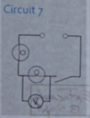
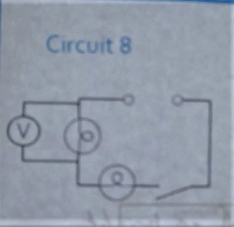
Circuit 6 was comprised of the transformer, the switch and then a parallel circuit with a voltmeter and bulb. When there was only one light bulb in the circuit, the voltmeter measured 12 volts. This showed that all the energy was being used by the singular light. In Circuit 7, another light was added between the parallel circuit and the transformer. Once the second light was added, the first light was only using 5.75 volts. This is due to the resistance of the added component. In Circuit 8, we moved the voltmeter to measure the second light bulb. The voltmeter only measured 5.25 volts being used by this light, showing that the resistance of the first light made the second dimmer.
Flipped Lesson 2 Notes:
Constructed series and parallel circuits Measured volts and amps using an ammeter and voltmeter Recorded changes in voltage, brightness and current when different components were added, removed of repositioned.
0 Comments
Electrical Circuits and Symbols Aim: To build series and parallel electrical circuits Keywords: Electrons, current, voltage, resistance, circuit Series circuit - stays the same Parallel circuit – splits equally and then re-joins going back to the battery What happens to current in a series circuit and a parallel circuit? A series circuit is a single loop in which the electrons must flow through all the components in the circuit to return to the battery. This means that if there are two light bulbs in a series circuit, then the electrons have to flow through both, increasing the resistance and meaning that the second bulb will be dimmer than the first. This also means that if one of the lights breaks, then the electrons will be unable to complete a full circuit and the other bulb will also not work. 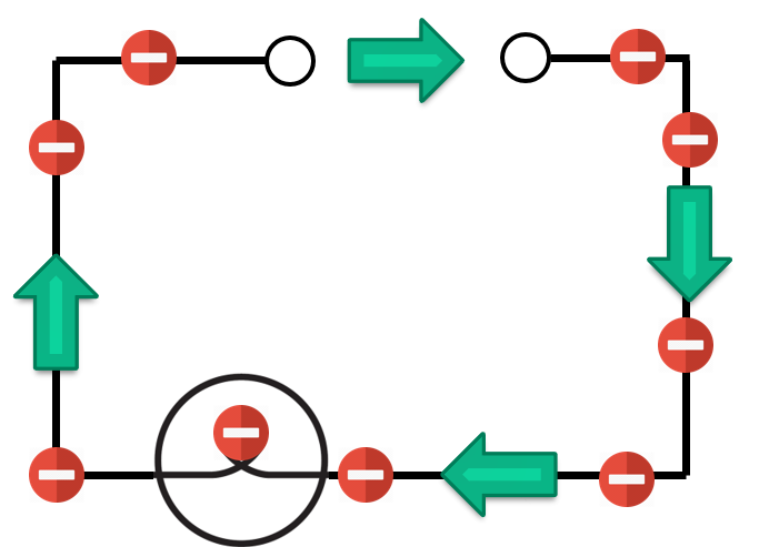 A parallel circuit includes a series circuit with another loop or circuit branching off and then connecting back, as seen below. In order for a voltmeter to operate properly, it needs to be parallel to the component, such as a light bulb. Due to the two separate loops, unlike a series circuit, if one component is destroyed or damaged, then the other is still able to operate. 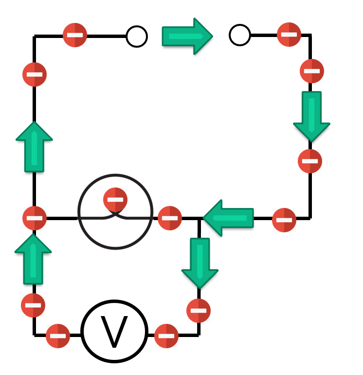 In this lesson we attempted to replicate electrical diagrams with real components, and to examine how they operated. We used and electrical transformer, some wires, an ammeter, a voltmeter and two light bulbs. We created simple series and parallel circuits and examined the effect that the added resistance had on the electrical components. In a series circuit, as more globes were added, the next consecutive light would become dimmer. This is because the first light was receiving the most energy, while all consecutive lights were receiving added resistance, reducing the energy that they received. However, in a parallel circuit, as more lights were added, no effect was visible. This is because the two separate loops allow energy to flow to each light independently, without the resistance of the previous light. Lesson Summary:
Constructed series and parallel circuits Examined the effect of resistance on electrical components Constructed a working ammeter and voltmeter, that allowed us to measure volts and amps. Symbols and Circuits Aim: To be able to identify common electrical symbols and what they represent: Keywords: Symbol, Circuit, Resistance Resistance: The repulsion of a current within a circuit. With more resistance in a circuit, less energy will flow through it. This lesson we learnt about a variety of electrical symbols and the physical components that they represent. We learnt how to draw an electrical diagram as seen below, and we also learnt the definition of current, volts, voltage, amps, ammeter and voltmeter. We also went on the website www.physics-chemistry-interactive-flash-animation.com, an interactive program in which an electrical circuit was generated using pictures of the components, allowing us to recreate them using the proper electrical symbols. 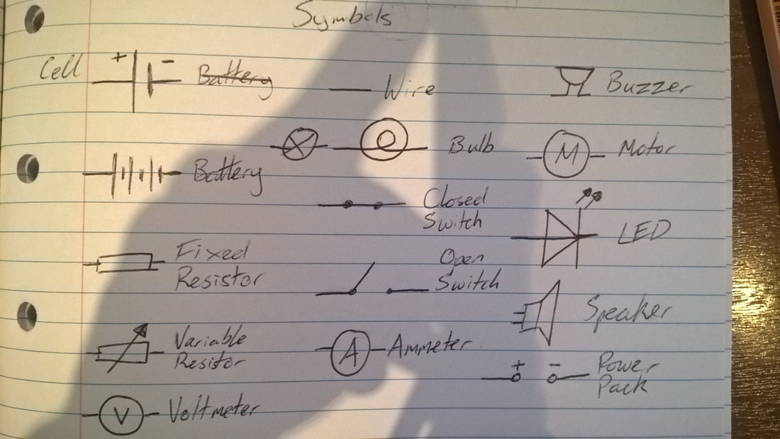  An electrical diagram illustrating a 6V battery (top), a light bulb (right), an ammeter (bottom) and an open switch (left). 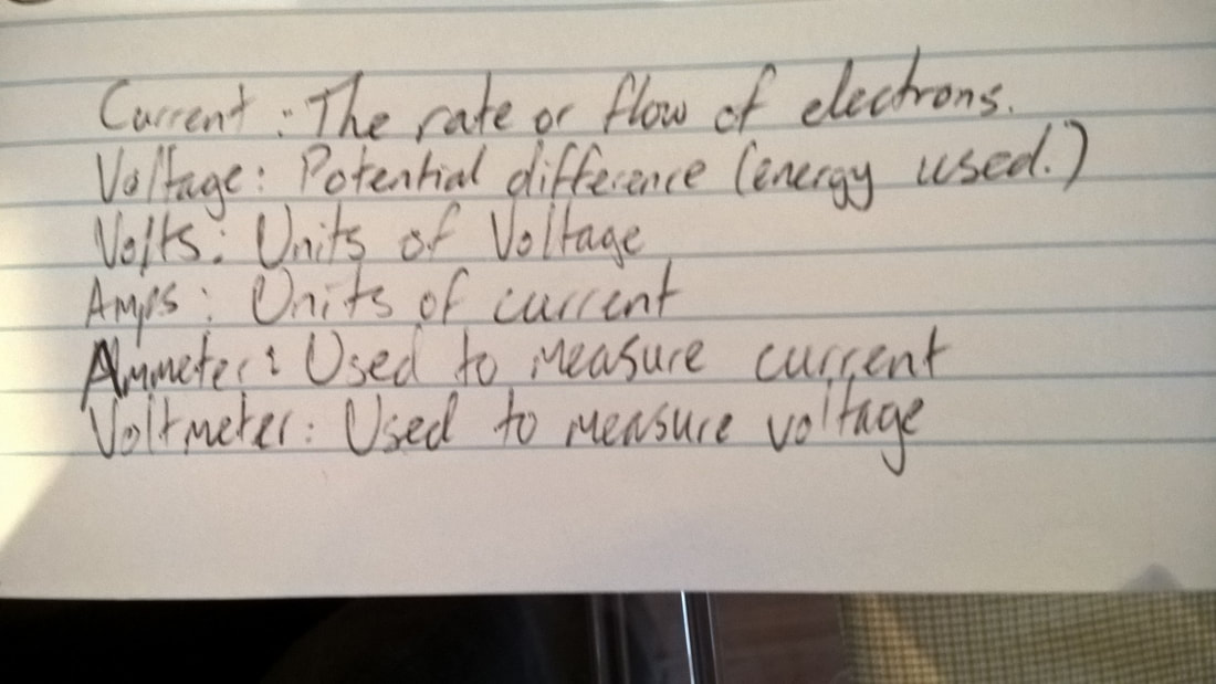 Lesson Summary:
Learnt a variety of electrical symbols and their meaning Learnt the definition of various words that can describe the flow and amount of electrons Learnt how to construct an electrical diagram using the proper symbols. Van de Graaff Generator Aim: To observe static electricity using a Van der Graaff generator Keywords: Electrons: A negatively charged particle Proton: A positively charged particle Neutron: A neutrally charged particle. This lesson we were shown a demonstration of a Van der Graaff generator. There were five specific demonstrations shown and they can be seen in the videos and images below. The first demonstration can be seen in the video “How a Van der Graaff generator works” below. This video explains how a Van der Graaff generator generates its electricity. The belt that can be seen in the video is revolving around two plastic pulleys. The negative charges or electrons are rubbing off of the pulleys onto the belt, causing the pulleys to become positively charged. Due to the fact that opposite charges attract each other, any negative charges on the metal spikes attempt to cross to the pulley, because of its positive charge. However, instead of reaching the pulley, the electrons are collected on the belt, before being brought up to the metal dome at the top of the generator. Once here, the charges have nowhere else to go, so they build up as “static electricity.” However, once thee small ball comes within the electric field, all of the electrons jump the gap at once, creating the “miniature lightning bolt” that can be observed. In the second demonstration, a metal rod with strands of fabric on the end was attached to the top of the generator. Once enough charge had built up, the electricity would flow into the fabric, causing each strand to become negatively charged. Due to the fact that they all have the same charge, each strand is repelled from each other and the generator, meaning that they appear to stand on end. The third demonstration involved a container filled with metal balls that had been coated in graphite powder, which was attached to the top of the generator. When the electricity passed into the container, it had a similar effect to the fabric. Each ball being negatively charged, caused them to repel each other, and levitate inside the container. In the fourth demonstration, a stack of foil cups was placed on top of the generator. Once enough electrons had built up, the repulsion caused the cups to fly off the top one at a time. The final demonstration, involved a two plastic tubes. One held an exposed wire connected to a light at the other end, and the other was filled with a gas. When the tube with the exposed wire was placed within the electric field of the generator, the light would activate. The second demonstration, with the tube hold gas, was wired by one end to the smaller conducting ball, and the other end to the tap, which acted as the earthing point. When enough charge passed through to the conducting ball, it flowed down the wire, into the tube, activating the gas and causing it to glow. This diagram below shows the flow of electrons when a person comes into contact with a Van der Graaff generator. The electrons that build up in the dome of the Van de Graaff generator, flow when a conductor is within their electric field. If someone touches the dome of the generator, then all the electrons will flow down their arm and into their body. Once the electrons are in the person’s body, they will eventually reach the person’s head. This means that all the hairs on the person’s body become negatively charged. Similar to the demonstration with the fabric, the hairs will repel each other and therefore stand on end. Note, that the energy stored within the person is “static” meaning that it is unable to flow anywhere. This is due to the foam mat that the person is standing on being a poor conductor or “insulator” of electricity. If the electricity was allowed to flow to earth, then this would shock the person, giving them an electric shock, so powerful, it could possibly kill them. 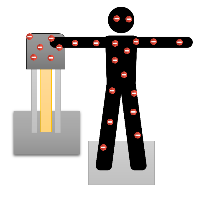 Lesson Summary:
Learnt how a Van de Graaff generator builds its electrical charge. Observed repulsion in action, through the demonstration with the cups and fabric Observed how attraction can cause energy to jump across air gaps Static Electricity Aim: To understand and describe static, repulsion and attraction Keywords: Static: A build-up of electricity due to the lack of a conductor for the energy to flow through Repulsion: The property that causes two objects with the same type of charge to repel or push each other away. Attraction: The property that causes two objects with different charges to attract or pull each other together. Proton: A positively charged particle. Electron: A negatively charged particle Neutron: A neutrally charged particle. Focus Question: Why do we get electric shocks? Electric shocks are caused when we transfer a large amount of either positive or negative energy onto an object with the opposite energy, or vice versa. When two objects rub or a pulled off each other, some of energy comes off, leaving one object with an excess of one type of charge and the other object with the opposite energy. If the energy has nowhere to go via a conductor, then it will build up, creating ‘static.’ This is the energy that is transferred when we get electric shocks. This lesson we learnt about static electricity, repulsion, attraction and their properties. We used the website ‘School for Champions’ to investigate how particles of different charges interact. This diagram shows two objects with differently charged particles. The object on the left is positively charged and the object on the left is negatively charged. We can see that their difference in charge is causing them to pull or ‘attract’ each other. This property is known as attraction. 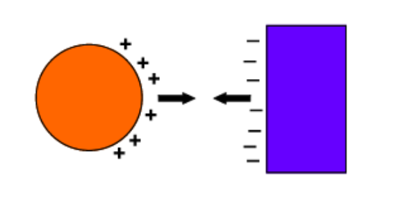 This diagram shows two objects, both of which are positively charged. The excess amount of a like charge is causing the two objects to push each other or ‘repel’ each other. This is known as repulsion. 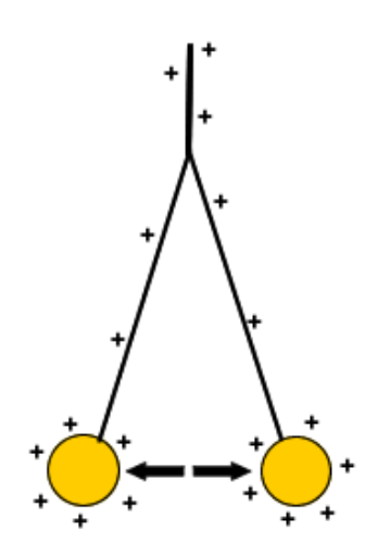 Lesson Summary
|