|
Flipped Lesson 5:
0 Comments
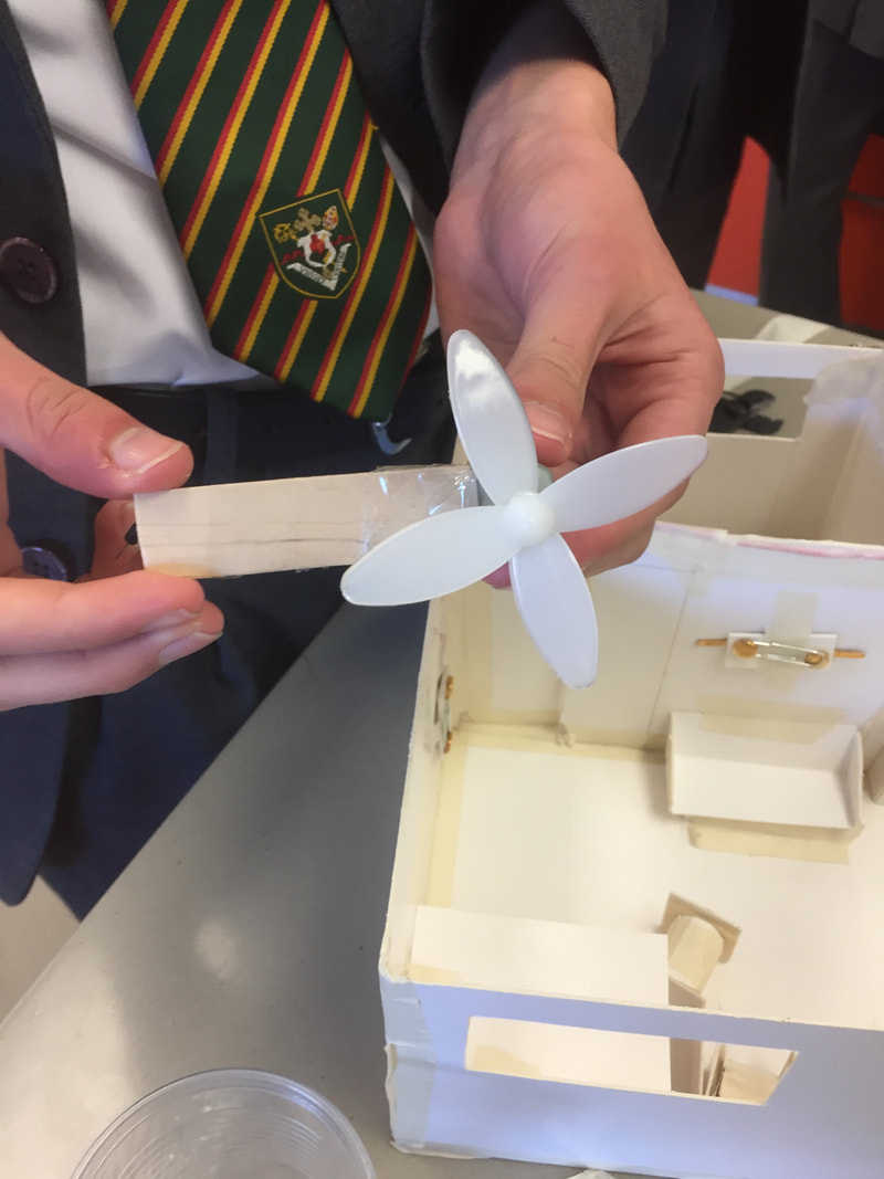
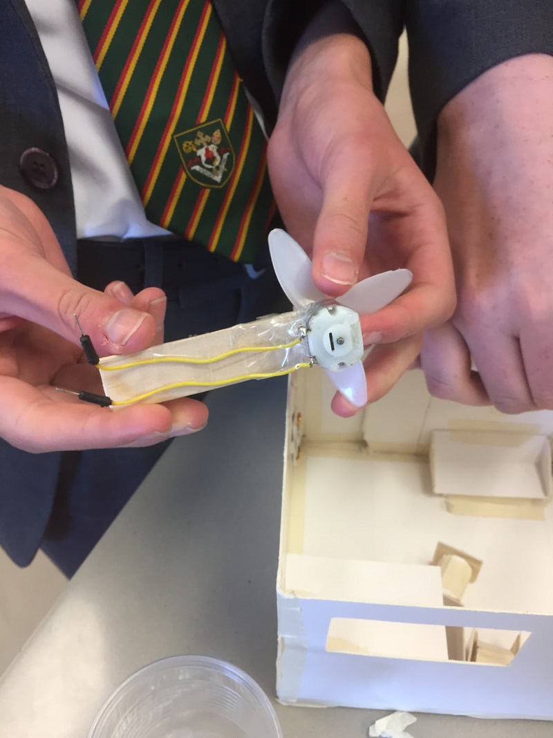
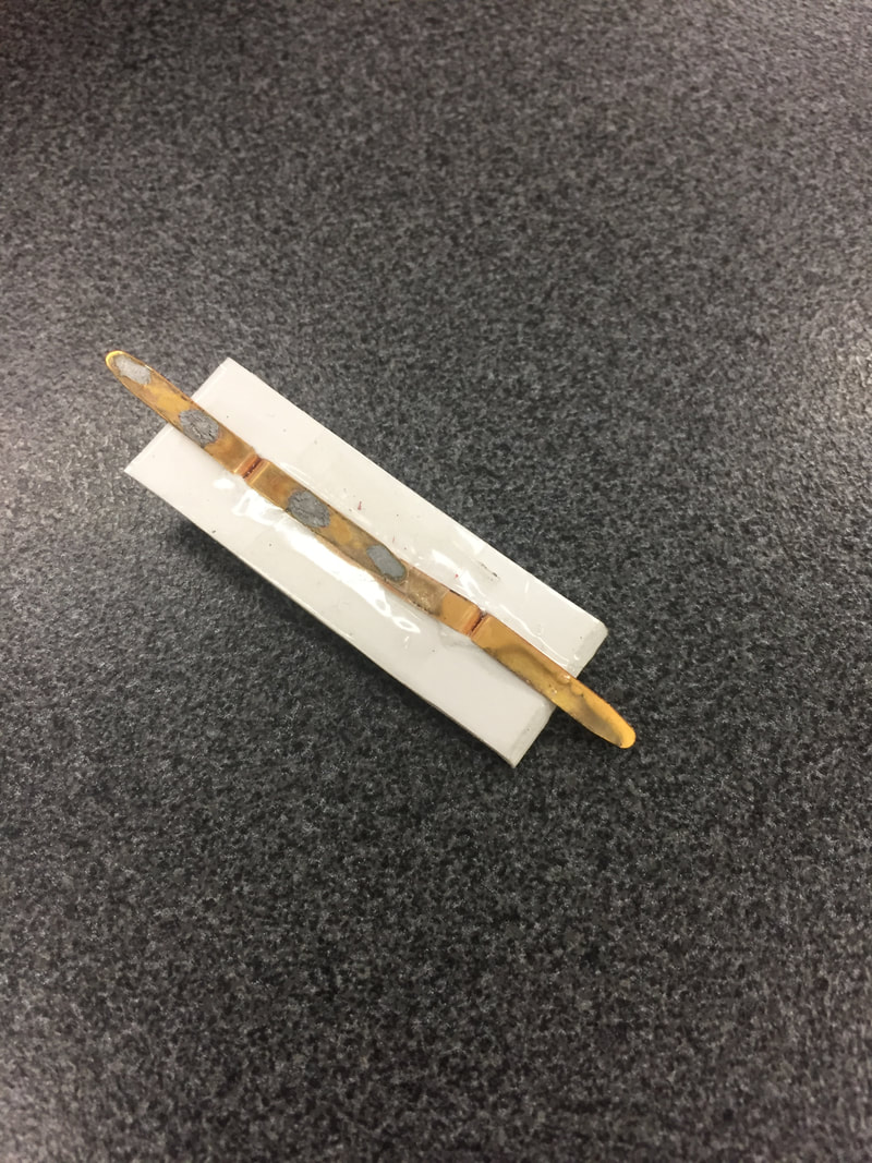
Circuit Building Aim: To continue constructing the circuit within our house Keywords: Parallel circuit, light emitting diode, series circuit This lesson we continued with the task of creating our electrical circuit that is to power the lights and other electrical components within our houses. The criteria in terms of components that have to be included in the house are: at least 2 lights (regular bulbs or LEDs) and at least 1 ‘other’ component. This other component can be literally anything that you would like as long as it runs on electricity. For our house we are including 4 LEDs and 1 ceiling mounted fan. As mentioned in previous blogs, the transformer doesn’t have the required voltage for LEDs, meaning we have to use a battery pack as our power source. This is an urgent issue to fix, as we are not using the lights that are being supplied, but 4 LEDs. Last lesson I mentioned the switches that we were using made of split pins and a paper clip, however an issue arose from the use of the switches and that is in order for the switches to allow the flow of electrons they must be held down. This becomes both annoying and impractical when operating the lights and fan, so instead we created a new switch which flows the same design, but the clip slides onto the pin, rather than having to be held down. This means that the electrical components can be activated without having to constantly hold them down, making them the much more practical switch. The fan that we have implemented into our house is ceiling mounted to allow better access to the wires and also improved aesthetics. Due to our house having no ceiling, the ‘ceiling’ mounted fan is actually mounted onto a piece of cardboard that is affixed to the wall via masking tape. This also means that the fan can be removed easily, to allow for adjustments to both its position and wiring.
Lesson Summary:
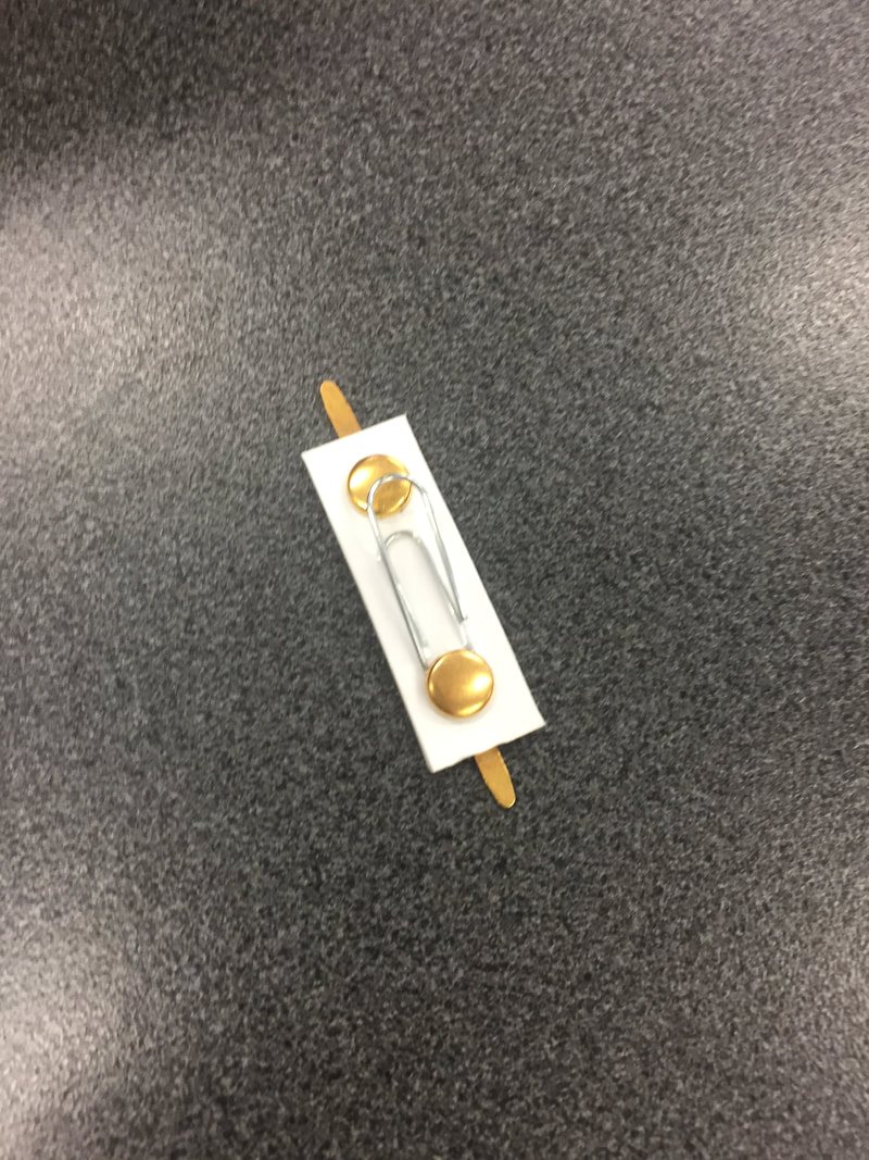
Attached our ceiling fan Created new switches and then attached 5 to the house Completed the input/negative side of our circuit. Creation Implementation Aim: To begin installing our electrical circuit into our house Keywords: Current, Voltage, Circuit, Parallel This lesson we began installing the negative or input wire into our house. As mentioned in the last blog, our use of LEDs means that we are unable to use the supplied transformer, due to unusable amounts of voltage. The LEDs require 3V to function and the transformer supplies from 2V to 12V, increasing by 2 each time, eg: 2, 4, 6, 8, 10, 12. In order to fix this issue, we will instead use a 3V battery pack as our power source, allowing our LEDs to function properly. We ran the wires along the walls of the house so that they both, do not hang down into any rooms and it creates a straight, neatly set out circuit that is easy to interact with and modify. Currently, we are using the switch shown in this image. It uses two split pins that have been punctured through a piece of cardboard. The pins are then split on the bottom, poking out of the side of the cardboard, in order to create input and output terminals. Finally, a paperclip is attached to one of the split pins and it is bent up. This means that when it is pushed down to touch the opposite split pin, electricity can flow. Note that on the underside of the switch, there is a piece of sticky tape separating the two split pins. This is to deny the flow of electrons directly from one split pin to the other, which would nullify the effect of the switch.
One problem that we will have to address in the future is the issue with our supply of wire. Each group is supplied with two lights, 1.5m of wire and any other little items that are required to construct the house. (Paper clips, masking tape, etc.) Although we were originally attempting to construct our input wire and conserve as much wire as possible, after constructing only half of our wire, we have used a large portion, approx. 60%-75%, of our wire. This may mean that we have to bring in our own wire from home, which should not be a problem, however we were hoping to complete the circuit with just the wire that had been supplied to us.
Lesson Summary: Constructed the negative/input half of our electrical circuit Discussed the advantages and disadvantages of using a battery pack over the transformer. Decided on the placement of electrical components within the house Circuitry Constructions Aim: To practise creating the electrical circuits that will be implemented into our house Keywords: Electrical circuit, components, motor, light, wire This lesson we attempted to construct the electrical circuit that will be implemented into our house, with the school electrical supplies, so that when it comes time to insert our circuit into the house, we will know how to connect all of the components, how much wire we will need and where each component will go. First of all, the components that we are using, as I mentioned in last lesson’s post, are four light bulbs, one motor, five switches, 1.5m of wire and a power source. We will be supplied with two light bulbs, however the other two lights will be LEDs. The LEDs that we have are only 3V and the transformer that is supplied increases by 2V starting at two. This means that going above 2V could blow the LEDs, but staying at 2 will mean that the LED won’t have the required energy to work properly. In order to fix this, we will not be using the transformer, but rather a battery with a 3V battery or two 1.5V batteries. The circuit that will be implemented into our house is a parallel circuit with 5 branches each with its own switch, 4 connected to a light bulb/LED and the 5th is connected to the motor. This is illustrated on the diagram below. 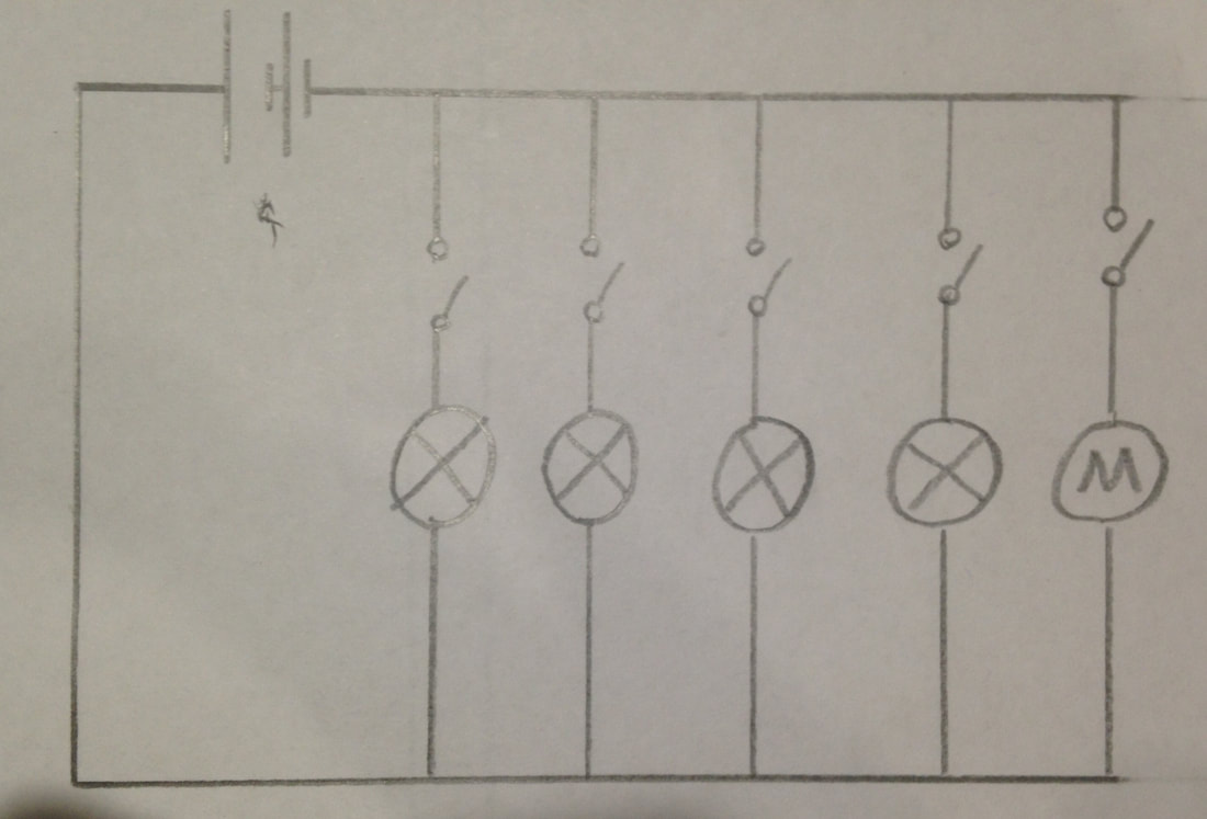  The intended positioning of our electrical components overlaid onto our house  A working example of the circuit that we are going to implement into our house. Lesson Summary:
Constructed a mock circuit according to the floorplan of the house Considered and decided on the electrical components that will be required Practised constructing circuits according to a corresponding electrical diagram. House Floor Plan Aim: To design and create a floorplan to be used when assembling and attaching the electrical components to our houses. Keywords: Light bulb, Circuit diagram, electrical component, transformer This lesson we constructed a floorplan for the house we created in Technology, to be used when it comes to having to fit our electrical circuit onto our house. We will be given two light bulbs, 1.5m of wire and the electrical transformer that we can implement into our circuit. However, we are also require to buy at least one other electrical component that has to be used in the house, but you can buy more if your design requires it. We will be using the two lightbulbs that are supplied, but we will also incorporate two LED’s and one motor into our design. The motor will act as a fan and a small object such as a section of a paddle pop stick will be attached to the motor to act as the blade of the fan. This image shows our current floorplan for the house, without the electrical components. On the grid, there are larger squares made of 64 smaller squares, equating to 8x8 squares. Each of these 82 is equal to 1cm2, with the total area of the house equaling 5cm x 5cm, 25cm2. All of our circuits were created digitally, on websites such as: http://www.smallblueprinter.com/sbp.html 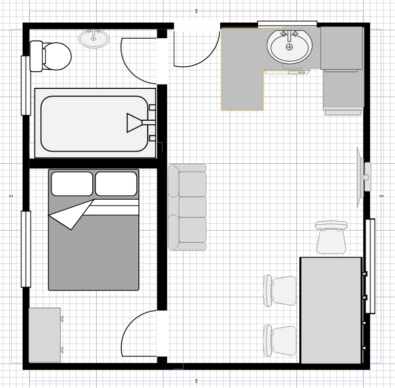 Lesson Summary:
Created and/or refined our house floor plans Discussed our requirements for the electrical components Discussed possible positioning for the electrical components in our house IntoScienceAim: To revise and complete the “Electrical Circuits” module on IntoScience Keywords: Current, voltage This lesson we continued on IntoScience to revise and understand the first STEM question for this week, “What is voltage and current?” and also the second STEM question, "How do we measure voltage and current within and electrical circuit." Below are my answers to these questions and also some images from the lesson. This graph illustrates the relationship between current and voltage. It demonstrates how as the strength of the electricity increases, logically, the strength at which it is flowing increases as well. The graph shows us that as more 1.5V batteries are added, the current increases by 0.15A. 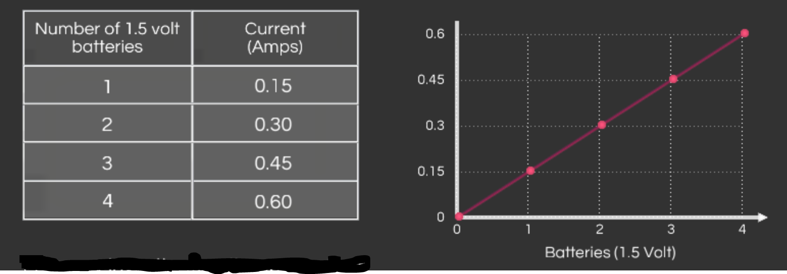 This graph illustrates how as more light bulbs are added and the resistance increases respectively, the current decreases. The table on the left shows us that each light bulb adds 10ohms, decreasing the current by from 60A, to 30A, then 20A and 15A. 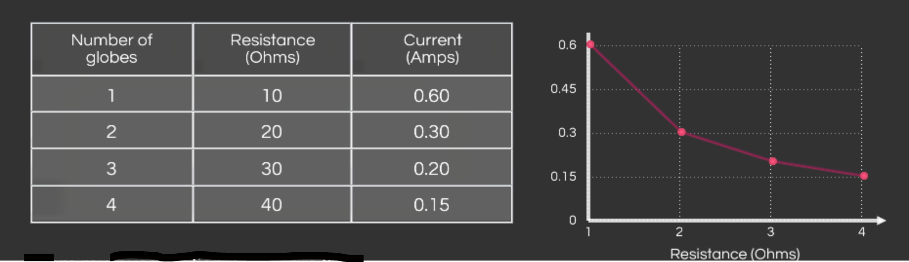 This final diagram, which also appeared in last week’s blog, is a triangle illustrating Ohm’s Law. This states that Voltage (V) = Current (I) x Resistance (R), as voltage is ‘over’ both current and resistance, illustrating that V/I = R and V/R = I, therefore concluding that V = I x R. 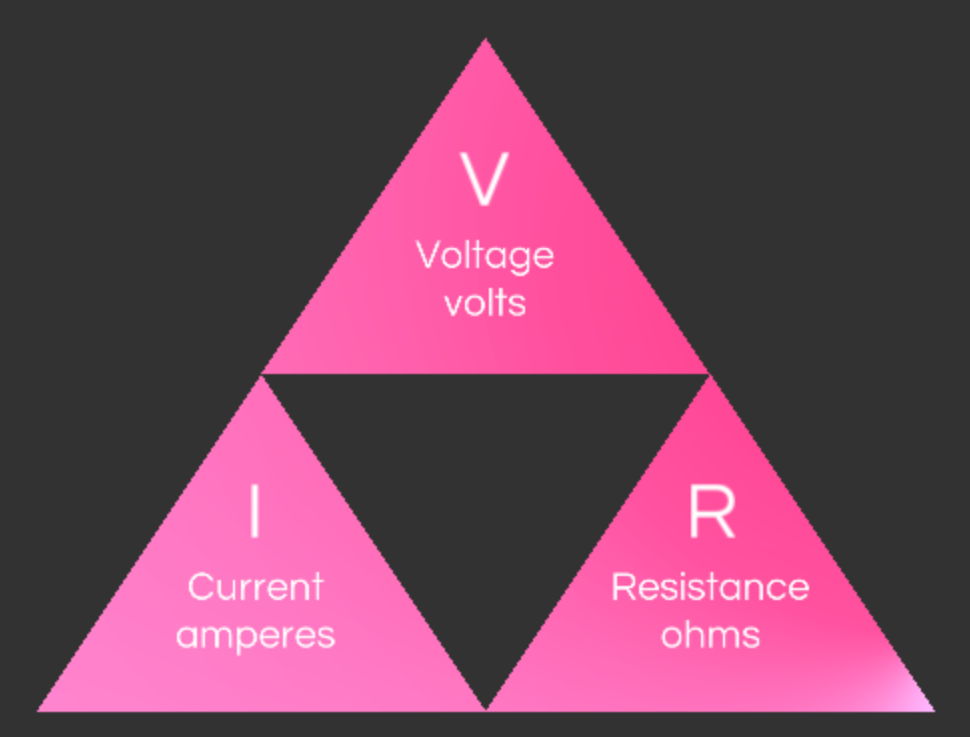 Stem Question 4: What is voltage and current?
Current and voltage are two interrelated characteristics of electricity. Although they are similar in ways and have large impacts on each other, they are two completely separate things. Voltage is the power or strength of the electrons and is measured in volts. A higher voltage means higher power and a higher risk when handling electricity. Voltage decreases as resistance increases, such as when more components are added to the circuit, as the electricity has to push through each component, losing its strength. Voltage will always decrease in a series circuit as the electrons have to flow through each component consecutively. However, in a parallel circuit which every branch only has one component, the voltage would remain constant. This is because, unlike the series circuit, the voltage doesn’t have to share itself amongst multiple components in the same branch. Current is the strength or ‘push’ of the flow of electrons, rather than the strength of the electricity itself. Current is measured in amperes or amps, and unlike voltage, current remains constant in a series circuit. This is due to a series circuit having only one path to flow down, meaning it is unable to split itself amongst conductors. Due to a parallel circuit having multiple branches for the electrons to flow down, current is shared equally among the branches in a series circuit. Stem Question 5: How do we measure voltage and current in a circuit? Voltage and current can be measured in a circuit using a voltmeter and an ammeter respectively. A voltmeter must be placed in parallel to the component it is measuring. This is because the voltmeter works by measuring the voltage at the input to the component and also the output. From this the voltmeter calculates the voltage and displays it on its dials as volts. (V) Current is measured using an ammeter and it must be placed in series with the component(s) in order to measure the current. Current is the flow of electrons and therefore the ammeter needs to be placed in circuit so that it can measure the current as the flow passes through it. The ammeter then displays this on its dial as amperes or amps. (A) Lesson Summary: Answered the question, “What is voltage and current?” Revised Ohm’s Law Revised the impacts that increases and decreases in voltage, current and resistance have on each other. |