House Floor Plan Aim: To design and create a floorplan to be used when assembling and attaching the electrical components to our houses. Keywords: Light bulb, Circuit diagram, electrical component, transformer This lesson we constructed a floorplan for the house we created in Technology, to be used when it comes to having to fit our electrical circuit onto our house. We will be given two light bulbs, 1.5m of wire and the electrical transformer that we can implement into our circuit. However, we are also require to buy at least one other electrical component that has to be used in the house, but you can buy more if your design requires it. We will be using the two lightbulbs that are supplied, but we will also incorporate two LED’s and one motor into our design. The motor will act as a fan and a small object such as a section of a paddle pop stick will be attached to the motor to act as the blade of the fan. This image shows our current floorplan for the house, without the electrical components. On the grid, there are larger squares made of 64 smaller squares, equating to 8x8 squares. Each of these 82 is equal to 1cm2, with the total area of the house equaling 5cm x 5cm, 25cm2. All of our circuits were created digitally, on websites such as: http://www.smallblueprinter.com/sbp.html 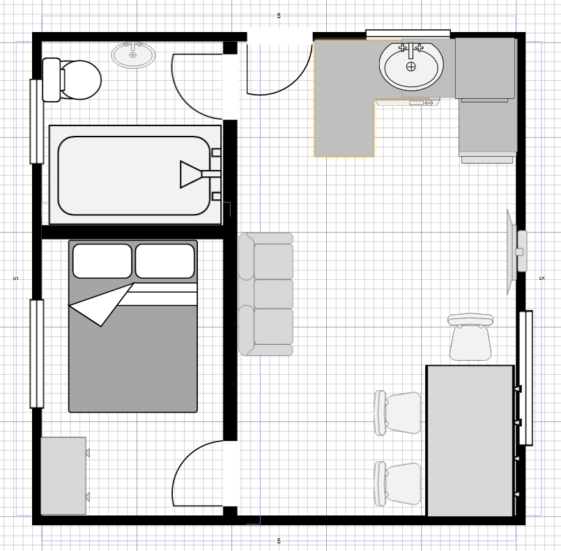 Lesson Summary:
Created and/or refined our house floor plans Discussed our requirements for the electrical components Discussed possible positioning for the electrical components in our house
0 Comments
Leave a Reply. |
