|
STEM Question 1: How can we construct a series circuit that has two functioning lights and a switch? A series circuit with two functioning lights and a switch can be easily constructed using four wires, a switches, a battery/transformer or other power source and two light globes. The first wire is connected from the power source to the switch. From here, the switch is connected to the first light, which is then connected to the second light, before being connected back to the power source. Being a series circuit and through the use of a single wire, the electrons only have one possible conductor to flow through. This means that all lights in the circuit will be activated when the switch is turned on. The completed circuit is illustrated below and can also be viewed at 6:30 of the “Using the School Electrical Kits” video. 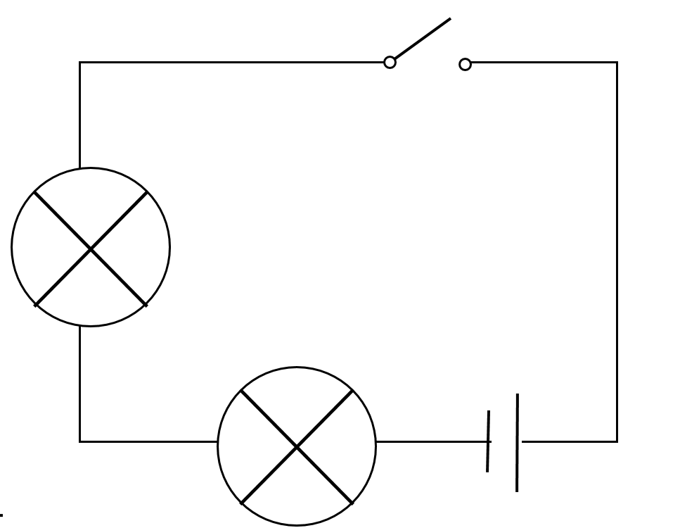 STEM Question 2: Why do we use electrical circuit diagrams? Electrical diagrams are used over regular drawings or sketches as it creates a well-structured, neat and clear diagram that is easy to interpret. Rather than have to guess what the illustrator is trying to draw with a regular sketch, circuit symbols are used in electrical diagrams and they are easy to draw and interpret. Another benefit of circuit diagrams is that wires are set out in straight lines, allowing for easier recreation when it comes to constructing the circuit in real life. STEM Question 3: How can a circuit be made that allows two bulbs to be switched on and off independently? A circuit can be constructed with two bulbs that are activated independently through the use of diodes. Diodes are a component that only allow electricity to flow in certain directions. This means that through the proper implementation of a diode, you can set up a singular circuit with two lights, each activated by their own switch. A quick example of this is evident in the “Two switch, two light circuit explained” video below.
0 Comments
Electrical Circuits Overview Aim: To revise and outline the key ideas and concepts of constructing and illustrating electrical diagrams. Keywords: Parallel, Series, Amperes, Volts, Current, Voltage This lesson, we revised our understanding of electrical circuits. Here are various diagrams and images of our lesson. First of all, we learnt about different ways to illustrate wires and batteries. The generic symbol for a single cell, is illustrated below and this generally represents 1.5V. This means that adding more cells is used to illustrate a battery of higher voltage. However, when representing a battery with a larger voltage, having to represent every 1.5V with its own cell can become extremely exhausting. This is why the symbol below, with the two cells separated by a dotted line was invented. This symbol represents a battery and you are able to write whatever voltage is necessary.  1.5V Cell (Top Left) 4.5V Battery (Top Right) Variable Battery (Bottom) We also learnt how to illustrate the three different types of wires. The first is the generic wire, illustrated by a straight line. The second is a cross, and this illustrates two overlapping wires that are not connected. The final symbol is a two wires, perpendicular to each other, with a dot where the wires meet. This symbol is used to illustrate two wires that are joined, with one breaking off the other. 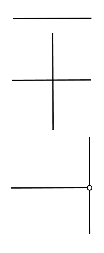 We then revised the relationships between current and voltage within series and parallel circuits. A series circuit, being a continuous line, means that the electrons have to flow through each component, reducing the voltage with each component added. However, due to there being only one path for the electrons to flow through, the current or amperes remains constant. A parallel circuit, on the other hand, is the complete opposite. The multiple paths for the electrons, means that the current is split evenly amongst each path and the individual paths also means that the voltage does not have to flow through each component individually, causing the voltage to remain constant. Finally, in this lesson we were introduced to the concept of “Conventional Current.” This was the way electrical diagrams were illustrated when people believed that energy flowed from the positive terminal to the negative and before the discovery of electrons. This means that the flow of electrons is illustrated in the opposite direction and the circuits are designed accordingly. If the circuit is constructed correctly, no matter how it is illustrated, the electrons will flow properly. Although “Conventional Current” does not illustrate the flow of electrons, it is still a valid way to construct a circuit diagram. 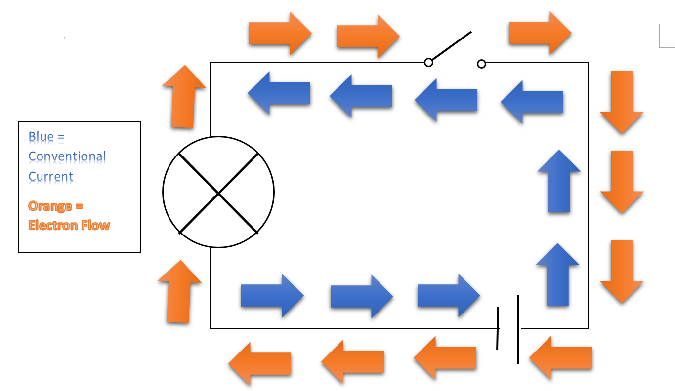 Lesson Summary:
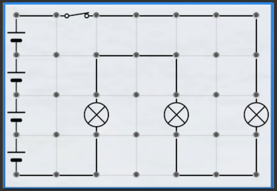
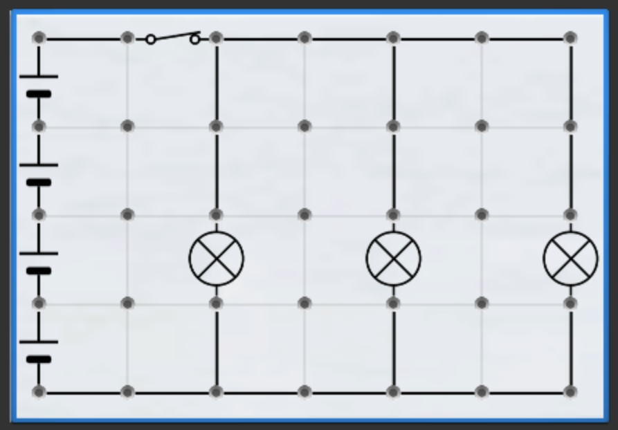
Learnt about “Conventional Current,” what it is and its similarities and difference when compared to electron flow. Revised our knowledge of parallel and series circuits, as well as current, voltage and resistance. Learnt specific ways to illustrate different types of wires and batteries. IntoScience Electrical Circuits Aim: To investigate and construct electrical circuits and diagrams, using the online program IntoScience. Keywords: Current, Voltage, Ohms, Ohm’s Law This lesson we went onto the online program, IntoScience, to investigate electrical circuits. We completed the module “Electrical Circuits,” and learnt about Ohm’s Law and the relationship between resistance, current and voltage. These diagrams below, illustrate a series circuit and a parallel circuit, each with exactly the same components, in the same position, however the wires are positioned differently. In the series circuit, the energy has to flow through each component, increasing the resistance and reducing the amount of energy each component receives. In the parallel circuit, the current flows through each component separately, meaning that they each receive a larger amount of energy than they would if they were arranged in a series circuit. The construction of a parallel circuit also means that if one electrical component is destroyed, the others will continue to work.
In this lesson, we also learnt about Ohm’s Law. This is illustrated in the triangular diagram below. Ohm’s Law describes the relationship between current, voltage and resistance and states that voltage (V) = Current (I) x Resistance (R), I = V/R and R -= V/I. 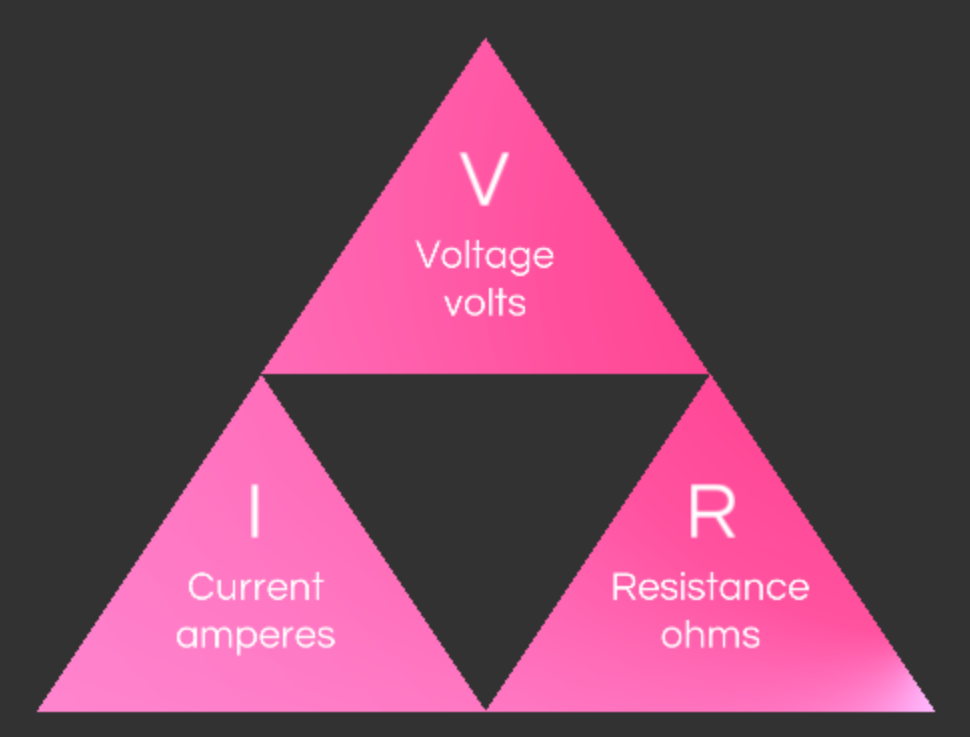 Lesson Summary:
Learnt about Ohm’s Law Learnt the proper measurement for measuring resistance, ohms. Constructed series and parallel circuits and their respective diagrams. Investigating Parallel Circuits Aim: To construct parallel circuits and illustrate their respective diagrams. Keywords: Parallel Circuit, Amperes, Volts, Ohms In this lesson, we constructed parallel circuits and measured the amps and volts at different points in the circuit. Both circuits followed a similar design, however they were modified according to the position of the ammeter or voltmeter. Evident below is an electrical diagram that illustrates the positioning of the ammeter. There were a total of three positions, the first in the first loop, the second in the furthest loop and the last on the common wire. When a total of 12V was input into the circuit a total of 0.5A was measured in each of the loops and 1A in the common wire. This is because the current has to divide itself amongst all of the possible conductor paths, in this case two, before meeting up again at the end. This meant that each loop got half the total current, at 0.5A, and the common wire got the full current at 1A. 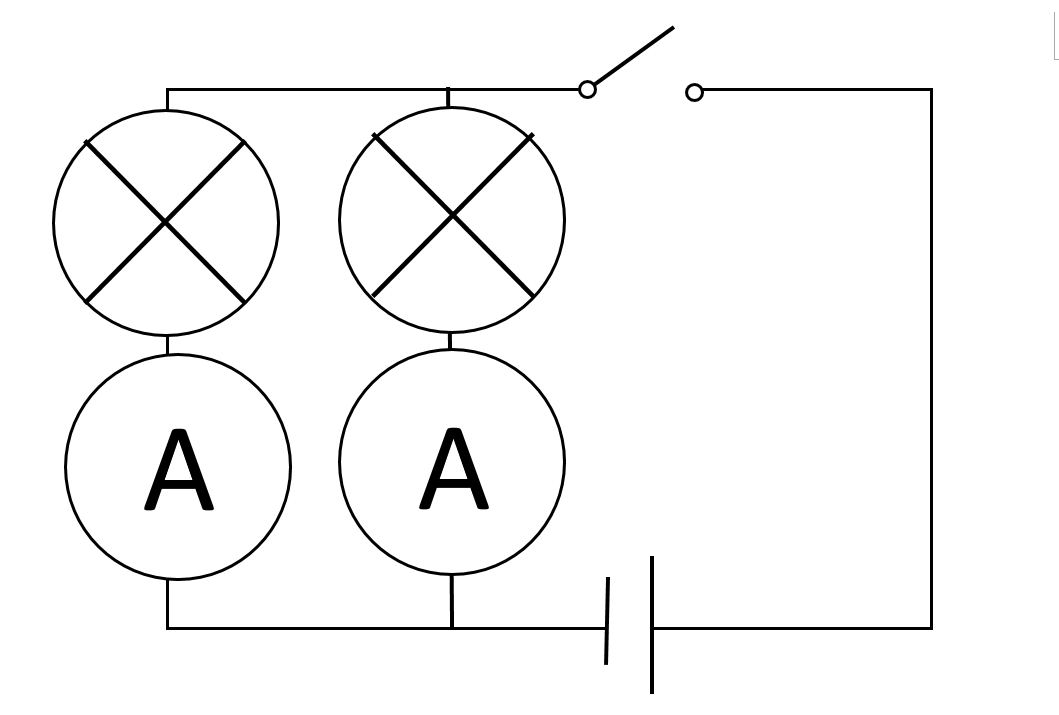 The second circuit was similar to the first, however the ammeters were replaced with voltmeters and parallel circuits were added where necessary. This can be illustrated below and the findings of the voltmeter were not at all similar to the findings of the ammeter. In a parallel circuit the current is split amongst all paths, however, due to the electrons not having to flow through each component consecutively, the volts remained constant at 12V. 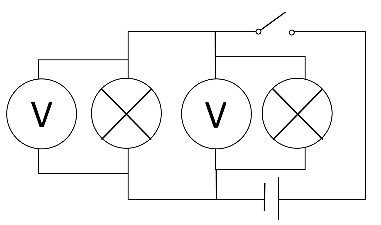 Lesson Summary:
Constructed parallel circuits Measured the volts and amps at different points in the circuits. Outlined the difference between a parallel circuit and a series circuit when it comes to current and voltage. |